116
P a r r I n s t r u m e n t C o m p a n y
Sample Collection Vessels
B
ottom drain valves can be added to most
Parr reactors. These valves are particularly
useful for those working with polymers or other
material that must be discharged from the
reactor while they are still hot and before they
can solidify. These valves are also quite useful
for the 1 gallon and larger vessels which are
too large to conveniently lift from the heater
for product recovery. Bottom valves are rarely
installed on the micro and mini reactors with
their small volumes and light vessel weights.
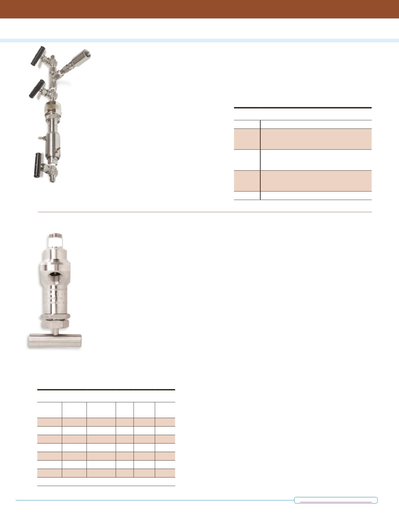
The standard bottom drain valve
has a
rising stem, that is flush with the inside cylinder
bottom so that there is no dead space between
the bottom of the vessel and the shut off point
of the valve. In the fully open position the stem
is retracted completely to open a clear passage
for draining the vessel.
When the valve is reclosed, any material in
this passage will be pushed back into the reac-
tor by the
rising stem.
Valves with
3/8" diameter
clear passage
are recom-
mended for
vessels with
volumes
from 1000
mL to 2
gallons. A
1/4" valve is
available for
600 mL and
smaller vessels. High pressure and larger diam-
eter valves are available where required.
These valves will withstand
the full operat-
ing pressures and temperatures of the vessels
in which they are installed. They are available
in nearly all of the current Parr materials of
construction. Air actuated valves are available
for larger reactors. Users can also specify that a
reactor ordered with a bottom valve shall have a
tapered bottom so that it will drain easily through
the valve opening.
Not all Parr reactors will accept a bottom
drain valve. Since the valve extends approxi-
mately 8 inches below the bottom of the vessel,
the entire vessel must be raised by this amount
to accommodate the valve. This makes some
models too tall for convenient bench top opera-
tion. The specification tables for each model will
identify those reactors in which a bottom drain
can be readily installed, and those which will
not accept a bottom drain, or those which will
require custom modification of the heater and
support stand to accommodate a bottom valve.
Needle Valves and Ball Valves
N
eedle valves and ball valves can also be
installed as bottom outlet valves. Needle
valves are generally used on the smaller reactors.
While ball valves can be used for large discharge
passages, they are generally limited in their
operating temperature/pressure capabilities and
they leave a fairly large dead space between the
bottom of the vessel and the seat of the valve.
Bottom Drain Valves
Part No.
Opening
Dia., in.
Outlet
Connection
Max.
Press.,
psi
Max.
Temp,
°C
Seal
A485VB 0.25
1/4" NPT (F) 3000 225
PTFE
A485VB2 0.25
1/4" NPT (F) 3000 350
Silver
A465VB 0.38
3/8" NPT (F) 2000 350
Grafoil
A465VB2* 0.38
3/8" NPT (F) 2000 350
Grafoil
A465VB3 0.38
3/8" NPT (F) 2000 350
Silver
A177VB 0.31
3/8" NPT (F) 5000 500
Grafoil
A296VB 0.69
1" NPT (F)
1900 265
PTFE
* Set up for a Band Heater.
Sample Collection Vessels
Part No.
Description
4351
Sample Collection vessel, 10 mL, with cooling
sleeve, isolation & vent valves for connection to
1/8”NPT valves
4352
Sample Collection vessel, 10 mL, with cooling
sleeve, isolation & vent valves for connection to
1/4”NPT valves
4353
Sample Collection vessel, 10 mL, with cooling
sleeve, isolation & vent valves for connection to
3/8”NPT valves
-D
Optional Drain Valve
A465VB Bottom
Drain Valve
A
sample collection vessel can be added to
most reactor systems. Designed to efficiently
and safely allow for the withdrawal of liquid or
vapor samples at elevated temperatures and
pressures, this quick close, O-ring seal vessel has
a volume of 10 mL and is designed for operating
pressures to 3000 psi (200 bar).
The typical arrangement for this sample ves-
sel includes a cooling sleeve, isolation and vent
valves. A drain valve may also be added to
the vessel.
The isolation valve is mounted at the head of
this vessel and is used to seal the vessel once the
sample is transferred. The vent valve is installed
in a tee and is used to release any residual pres-
sure in the line between the sample valve and the
sample vessel. Samples can be removed either
by opening the collection vessel and pouring it
out or by use of the drain valve.
Standard material of construction is T316
Stainless Steel but it can be provided in any of
the other alloys if required. A high pressure sam-
ple collection vessel without a cooling sleeve for
pressures to 5000 psi is available upon request.
Bottom Drain Valves


