6
P a r r I n s t r u m e n t C o m p a n y
w w w . p a r r i n s t . c o m
Series 5400 Continuous Flow Tubular Reactors
Below and right are schematic
representations of typical tubular
reactor systems, along with a symbols
chart to facilitate understanding. We
have provided the ordering number
for each of these examples.
Order No.: 5402C-SS-115-FM-
1500-DCS-GF(1)-PL-LF(1)-ITW-CHX-
GLS(300)
Order No.: 5403F-SS-230-ST3(24)-3000-
PCC-GF(2)-PL-LF(1)-ISP-CSS-ITW-GLS(600)-
TR(3)-AP-ASV
Tubular Reactor System with Three-Zone Heater,
600 mL Separator Vessel and 4871 Controller
Single-zone Tubular Reactor System with
one Liquid Feed, one Gas Feed, and a Purge
Line.
GAS 1
S
Purge
PT
T/C
T/C
T/C
BPR
Vent
T/C
Gas1
S
MFC
F
Gas 2
S
MFC
F
Liquid
4871
Process
Controller
PIC
PG
Gas
FIC
Gas
Liquid
F
F
F
MFC
T/C
PT
T/C
TIC
Key to Symbols
Inlet
PG
Pressure Gage
PI
Pressure Indicator
PT
Pressure
Transducer
T/C
Thermocouple
FIC
Flow Indicating
Controller
PIC
Pressure Indicating
Controller
Ball Valve
Metering
Rupture Disc
3-way
Check Valve
Relief Valve
F
Filter
MFC
Mass Flow
Controller
SIC
Speed Indicating
Controller
MFM
Mass Flow Meter
TIC
Temperature
Indicating
Controller
Pump
Tank Pressure
Regulator
Back Pressure
Regulator
S
Electric-Actuated
Air-Operated
Solenoid Valve
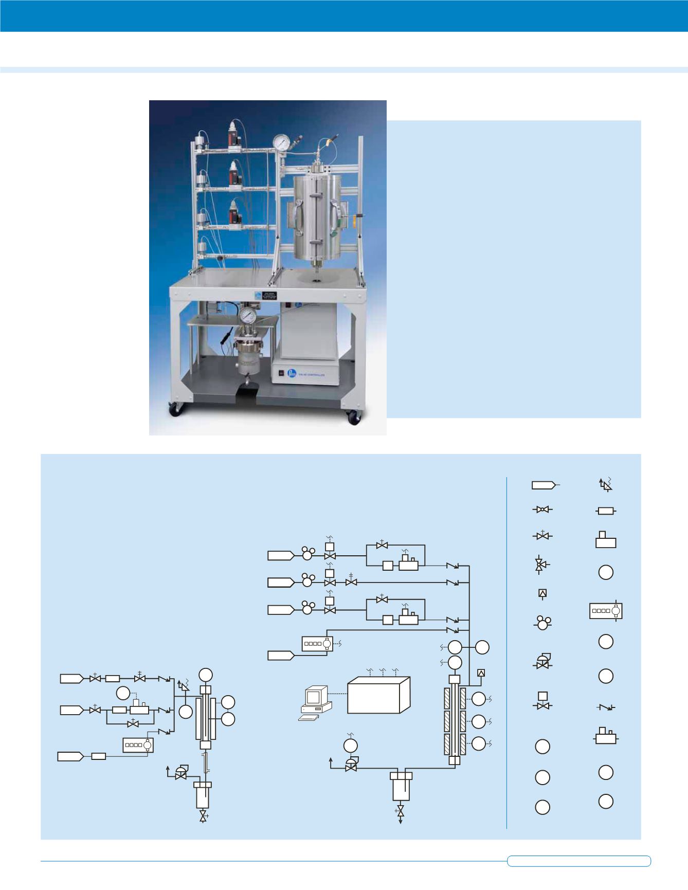
< Synthesis gas (H2/CO) related chemistry is studied with this
30 cm long tubular reactor. This system features the following
main system components:
Three gas mass flow controllers for hydrogen, carbon
monoxide and carbon dioxide. Each MFC is equipped with an
automated air piloted valve to ensure a positive shutoff of the
reactant gas flow.
The 2.5 cm ID reactor and its associated single zone heater.
The reactor is rated for use up to 100 bar @ 550 ˚C and is
equipped with an internal pre-heater and catalyst spools for
easily changing the catalyst loading.
A jacketed gas/liquid product separator coupled with an
automated back pressure regulating system. The jacket is
used for cooling the reaction products.
The process controller and valve interface are conveniently
located on the lower shelf of the moveable reactor stand.
The system was provided with a high pressure liquid meter-
ing pump (not shown) to optionally introduce liquid reactants
into the reactor.
This system is used primarily to facilitate the study and
development of industrial scale catalysts from biomass ash
and char, focusing on engineered manipulation of the char
structure and surface to enhance catalytic activity and selec-
tivity. The emphasis is on catalysts for the synthesis of liquid
fuels and chemicals such as the conversion of synthesis gas
to mixed alcohols.
Reactor Schematic Examples and
their Respective Order Numbers


